What is Error-Control in networking?
AfterAcademy Tech
•
04 Feb 2020
While sending the data from the sender to the receiver there is a high possibility that the data may get lost or corrupted. Error is a situation when the sender's data does not match the data at the receiver's end. When an error is detected then we need to retransmit the data. So, there are various techniques of error control in computer networks. In this blog, we will see all these techniques. So let's get started.
Error Control
Error Control in the data link layer is a process of detecting and retransmitting the data which has been lost or corrupted during the transmission of data. Any reliable system must have a mechanism for detecting and correcting such errors. Error detection and correction occur at both the transport layer and the data link layer. Here we will talk about the data link layer and check bit by bit that if there is any error or not.
Types of error
Single bit Error: When there is a change in only one bit of the sender's data then it is called a single bit error.
Example: If the sender sends 101(5) to the receiver but the receiver receives 100(4) then it is a single bit error.
101(sent bits) → 100(received bits)
Burst Error: When there is a change in two or more bits of the sender’s data then it is called a burst error.
Example: If the sender sends 1011(11) to the sender but the receiver receives 1000(8) then it is a burst error.
1011(sent bits) → 1000(received bits)
Phases in Error Control
- Error Detection: Firstly, we need to detect at the receiver end that the data received has an error or not.
- Acknowledgement: If any error is detected the receiver sends a negative acknowledgement(NACK) to the receiver.
- Retransmission: When the sender receives a negative acknowledgement or if any acknowledgement is not received from the receiver sender retransmits the data again.
Error Detection
- Vertical Redundancy Check
- Longitudinal Redundancy Check
- Circular Redundancy Check
- CheckSum
Vertical Redundancy Check(VRC)
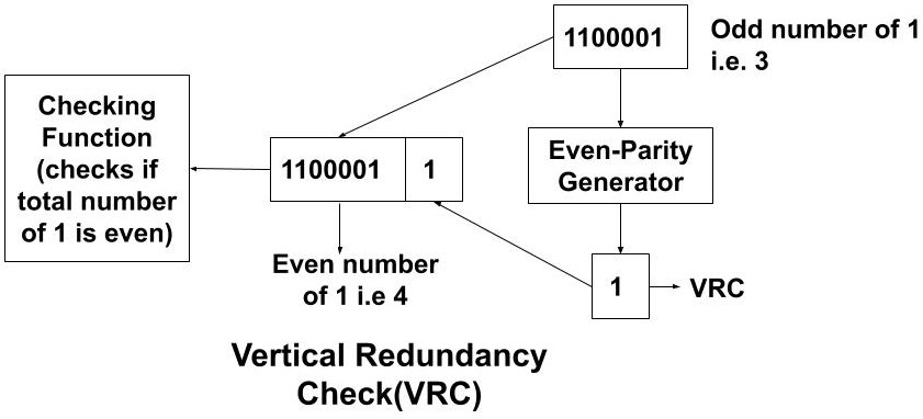
In this method, a redundant bit called parity bit is added to the data. This parity bit is added such that the number of 1’s in the data is even. This is called even parity checking. If the number of 1’s is even then the bit to be added is 0. If the number of 1's is odd then the bit to be added is 1.
Some systems may also check for the odd number of 1’s. This is called odd parity checking. If the number of 1’s is odd then the bit to be added is 0. If the number of 1's is even then the bit to be added is 1.
Example: We have a data 1100001. Now, this data is sent to the even parity generator which adds a redundant bit to it by checking the number of 1's. The even parity generator will add a 1 as it has odd numbers of 1’s. So, the data which is going to be transmitted is original data along with the parity bit i.e. 11000011. At the receiver side, we have a checking function that checks if the number of 1’s is even or not.
Limitation of VRC
Suppose in the above example, if at the transmission time two bits are altered such that the receivers receive the data as 10000001. The receiver will successfully accept this data. This is because the checking function will check for an even number of 1’s and the received data will satisfy this condition.
So, VRC fails when there is an even number of changes in the data.
Longitudinal Redundancy Check(LRC)
In LRC we use a block of codes as the parity bit. We will take each block of data and calculate the parity bit longitudinally instead of vertically. The sender will send the original data along with the block of parity bit generated. This can be understood by the example below.
Example: Suppose we have to send the data, 11100111 11011101 00111001 10101001. So we will calculate the parity bit by using even parity checking. We will start from the zeroth position of each block of bits and gradually move towards the higher positions. We take all the bits present in the zeroth position i.e 1, 1, 1, 1. Now, the output is decided according to the following two rules:
- If there are even number of 1's then the output will be 0.
- If there are odd numbers of 1's then the output will be 1.
As '4' 1's are present which is an even number so the output at the zeroth position will be 0 and so on for the higher positions.
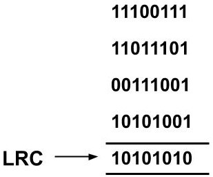
The transmitted data will be 11100111 11011101 00111001 10101001 10101010.
Limitation of LRC
Suppose in the above example, during transmission some of the bits get changed and the received data is 11100111 11011101 00110011 10100011. If we calculate the parity bit for this received data then it will again come out to be 10101010 at the receiver's end.
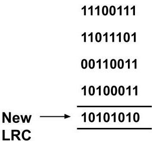
So even if the data bits have changed this error won't be detected at the receiver's end.
So, if two bits in one data unit are damaged and the two bits at the exact same position in another data unit are damaged the LRC will not be able to detect it.
Checksum
There are two processing methods involved in this. The sender generates the checksum and sends the original data along with the checksum. The receiver end also generates the checksum from the received data. If the generated sum at the receiver side is all zeroes then only the data is accepted.
The sender follows these steps:
- Data is divided into k sections or blocks of given ‘n’ bits.
- All the sections are added using 1’s complement(data).
- The final sum is bitwise complemented(convert 0 to 1 and 1 to 0) to get the checksum.
- The sender sends the original data along with the checksum.
The receiver follows the following steps:
- Data is divided into k sections or blocks of given 'n' bits.
- All the sections are added using 1’s complement(data+checksum).
- The final sum is bitwise complemented(convert 0 to 1 and 1 to 0).
- If the result is all zeros then it accepted else rejected.
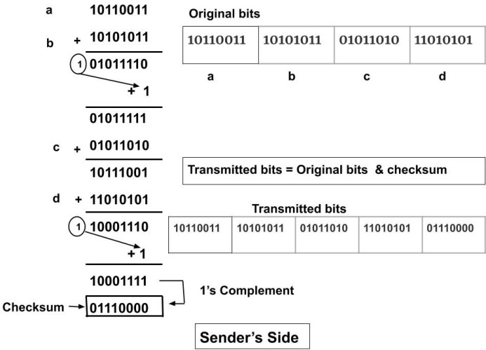
Example: We have to send the data where data is divided into four sections each of 8 bits. Suppose we have to send 10110011 10101011 01011010 11010101. So, there are 32 bits and we will divide the whole 32 bit data into a group of 8 bits i.e. 4 groups.
In the sender's side
- Take any two blocks of data and perform 1's complement arithmetic.
- Take the next block of data and add it to the result of the last addition. Perform the addition until all the blocks are added.
- Take 1's complement of the last sum obtained. It is a checksum.
- Transmit the original bits along with the checksum to the receiver's side.
In the receiver's side
- Take any two blocks of data and perform 1's complement arithmetic.
- Take the next block of data and add it to the result of the last addition. Perform the addition until all the blocks are added.
- Take 1's complement of the last sum obtained. If the complement is all zeros then only the data is accepted. Here, the result is all zeros hence the receivers accept the data.
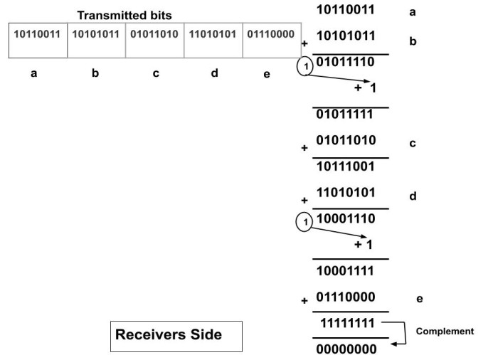
Since the result is 00000000. So, the received data is correct.
Cyclic Redundancy Check(CRC)
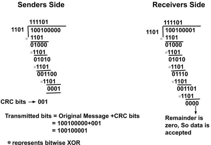
The cyclic redundancy check is based on binary division. The sender and the receiver both agree upon a generator polynomial. A generator polynomial can be any polynomial expression. This generator polynomial helps in finding the CRC generator. CRC bit(having the same number of bits as the CRC generator) is generated at the sender's side by dividing the bit sequence of the data by the CRC generator. Before dividing the bit sequence by the CRC generator we will append the original data with n-1 bits of 0's assuming that the CRC generator has n bits. The sender will then append the data with the CRC bit and send it to the receiver.
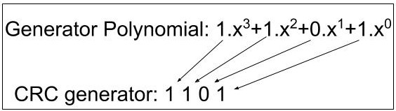
Example: Given any generator polynomial, we can find the CRC generator by taking the coefficient of each variable.
At the receiver end, the received bits are divided again by the CRC generator. If the remainder of the division is zero then the data is accepted else rejected.
Example: We have our data as 100100. The generator Polynomial is as in the above explanation i.e. 1.x^3+1.x^2+0.x^1+1.x^0. So, our CRC generator will be 1101(4 bits). Now, we have to append the original data with n-1 numbers of 0’s where 'n' is the number of bits in the CRC generator. Here n is 4. So, the dividend is 100100000(i.e. 100100 and 000) and the divisor is 1101. Now while dividing we will perform the XOR operation as follows. This division will be performed on both the sender and receiver sides. For the receiver side, the divisor would be the same and the dividend would be the original data along with the CRC bits. If the remainder at the receiver side is zero then only the data is accepted.
Retransmission
When any error is detected then the specified frames are sent again this process is called automatic repeat request(ARQ). Error Control in the data link layer is based on the ARQ.
The following error control techniques can be used once the error is detected.
- Stop and wait ARQ
- Sliding Window ARQ
Stop and Wait ARQ
A time out counter is maintained on the sender's side. Firstly, if the sender does not receive the acknowledgement of the sent data within the given time then the sender assumes that the sent data has been lost or the acknowledgement of the data has been lost. So, the sender retransmits the data to the receiver. Secondly, if the receiver detects an error in the data frame indicating that it has been corrupted during the transmission the receiver sends a NACK(negative acknowledgement). If the sender receives a negative acknowledgement of the data then it retransmits the data.
Sliding Window ARQ
In sliding window ARQ, a sender can send multiple data frames at the same time. The sender keeps a record of all the sent frames until they have been acknowledged. The receiver can send an ACK (acknowledgement ) or NACK(negative acknowledgement) depending upon if the data frame is received correctly, if any error has been detected, or has been lost.
The sliding ARQ is of two types:
- Go-Back-N ARQ
- Selective Repeat ARQ
Go-Back-N ARQ
In this protocol, if any frame is lost or corrupted then all the frames since the last frame that was acknowledged are sent once again. The sender's window size is N but the receivers window size is only one.
Example: Suppose we have a window size of 4 for the data frames which we are going to send. Now, suppose while sending the data frame 2 some error occurred and it got corrupted. So the receiver will send a negative acknowledgement (NACK) of the data. All the data frames after the last acknowledged(ACK) frames i.e after frame 1 will now be sent again.
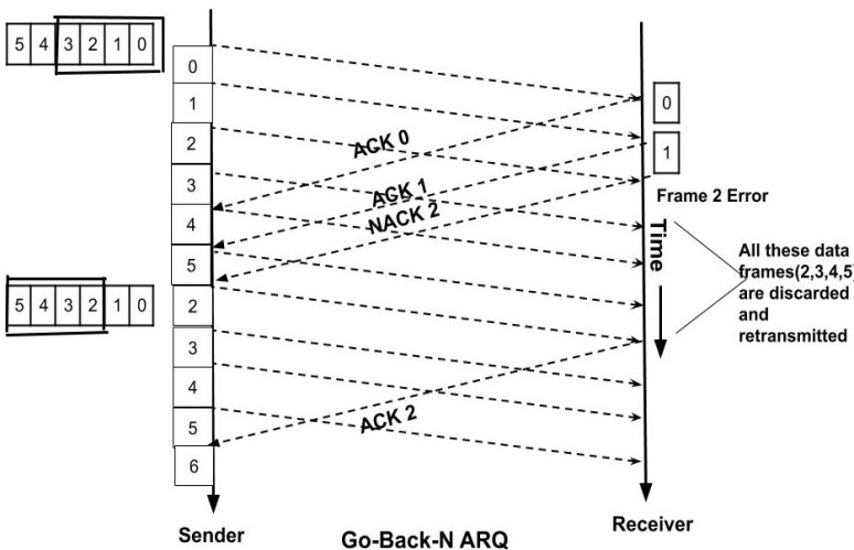
Limitations of Go-Back-N ARQ
In this, we have to send all the frames once again even though it has no errors. In the above example, we had to send all the frame i.e 2, 3, 4, 5 once again though the error was only in frame 2. How we can overcome this?
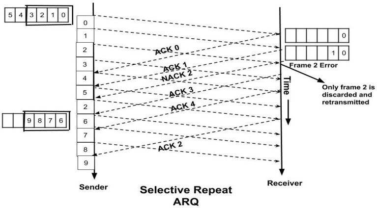
Selective Repeat ARQ
In this ARQ, if any frame is lost or corrupted then only that frame is sent again which has a negative acknowledgement. The sender’s window size and the receiver’s window size is the same here.
It removes the problem of the Go-Back-N ARQ as the error-free frames can be accepted as the receiver's window size now equal to the sender's size, unlike the Go-Back-N ARQ where the receiver's window size was only 1. The retransmission method is modified as only the individual frames are retransmitted.
Example: In the above example, if there was an error in the frame 2. So, we will send only the frame number 2 again.
This is how the error control is done in networking. Hope you learned something new today.
Do share this blog with your friends to spread the knowledge. Visit our YouTube channel for more content. You can read more blogs from here.
Keep Learning 🙂
Team AfterAcademy!
Written by AfterAcademy Tech
Share this article and spread the knowledge
Read Similar Articles
AfterAcademy Tech
What is Flow-Control in networking?
In this blog, we will learn what is flow control, what happens when the sender and receiver work at a different speed. We will also discuss the flow control methods to control the flow of data between the sender and the receiver.

AfterAcademy Tech
What is a network and what are the nodes present in a network?
In this blog, we will mainly learn about a computer network and its node. We will also cover the classification, goals, and applications of a computer network.
AfterAcademy Tech
What is network topology and types of network topology?
In this blog, we will learn about various network topologies, their advantages and disadvantages in a computer network.

AfterAcademy Tech
What are Peer-to-Peer networks and Server-Based networks?
In this blog, we will learn about the types of network based on design, that are Peer-to-Peer, and Server-Based networks. We will also see the applications, advantages, and disadvantages of using these networks.